
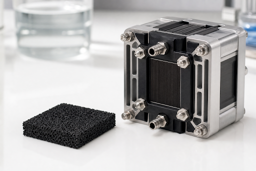
Hydrogen electrochemical devices depend on more than the catalyst itself. The support and catalyst layer must create usable pathways for reactants, products, ions, electrons, and heat. Materials such as nanoporous carbon can offer a large internal interface, but electrode performance ultimately depends on whether that interface remains accessible during operation.
Pore architecture describes the size, shape, volume, connectivity, and winding nature of the empty spaces within a material. It determines whether an electrode behaves like an open transportation network or a crowded maze. A structure can contain many pores yet still underperform if the pathways are blocked, poorly connected, too narrow for key components, or altered during catalyst coating and cell assembly.
Why Pore Architecture Matters
A catalyst support has several jobs at once. It can disperse catalyst particles, provide electrical contact, help retain the catalyst layer, and create space for fluids and gases to travel. These functions are interdependent. Increasing density may improve electrical contact, for example, but it can also reduce open volume and make mass transport more difficult.
Connectivity is especially important. An isolated pore contributes little to through-plane transport, whereas connected pores can provide routes from flow channels to reaction sites. Tortuosity, meaning how indirect a path is, also matters. Longer, more winding routes can increase resistance to gas or liquid flow and contribute to local concentration differences.
How Pores Control Transport
Inside a working electrode, several species move at the same time. Hydrogen or oxygen must reach reaction sites in a fuel cell. Water must reach active sites in an electrolyzer. Protons, hydroxide ions, or other charge carriers move through the electrolyte phase, while electrons travel through conductive solids. Products must also leave quickly enough to prevent local blockage.
- Gas diffusion: Reactant gases require open pathways to reach the active sites in the catalyst layer.
- Water movement: Water must be retained or removed in the right amount for the device and operating conditions.
- Ion transport: The ion-conducting phase must contact catalyst sites without creating excessive resistance.
- Electron transport: Conductive pathways must connect catalyst particles to current collectors.
- Product removal: Liquid water, hydrogen, oxygen, and heat must move away from the reaction zone.
Surface Area Versus Accessibility
Specific surface area is useful, but it is not a complete performance metric. Some very small pores may be difficult for catalyst particles, ionomer, liquid water, or reactant gases to enter. Surface within those locations can appear in an adsorption measurement while contributing little to practical electrochemical activity.
Questions That Test Usable Surface Area
- Can the reactant enter the pore under operating conditions?
- Can the ion-conducting phase reach the catalyst site?
- Can products leave without accumulating?
- Will the pore remain open after catalyst deposition, drying, compression, and cycling?
- Does the support keep the catalyst electrically connected and mechanically stable?
Pore Design in Hydrogen Fuel Cells
In hydrogen fuel cells, cathode design is often strongly influenced by oxygen transport and water management. At higher current demand, oxygen must pass through the gas-diffusion medium and catalyst layer quickly enough to sustain the oxygen reduction reaction. At the same time, generated water cannot be allowed to fill critical gas pathways.
Small pores can help anchor finely dispersed catalyst particles, while larger, connected pores can facilitate gas flow and product-water removal. For this reason, hierarchical structures containing more than one pore scale are often attractive. Recent work on interconnected macroporous carbon structures illustrates how electrode architecture can improve mass transport for platinum-group-metal-free cathodes, particularly in thicker catalyst layers that pose additional transport challenges.
Pore Design in Electrolyzers
Electrolyzers reverse the overall fuel-cell reaction by using electricity to split water into hydrogen and oxygen. In a polymer electrolyte membrane system, water is supplied to the anode, where oxygen forms; protons move through the membrane; and hydrogen forms at the cathode. The U.S. Department of Energy explains how electricity splits water into hydrogen and oxygen via electrochemical pathways.
Porous electrode design in electrolyzers must support liquid-water access while allowing gas bubbles to disengage. Persistent bubbles can cover active regions and raise local transport resistance. Pore geometry also affects liquid flow, pressure drop, electrical contact, and the electrode’s ability to tolerate changes in gas production rates.
Fuel Cell and Electrolyzer Priorities
- Fuel cells: Main reactants are hydrogen and oxygen. Major risks include oxygen starvation and flooding. Open gas pathways and balanced wetting are central design needs.
- Electrolyzers: The main reactant is water. Major risks include limited water supply and bubble blockage. Fast liquid access, conductive contact, and bubble release are central design needs.
Key Material Properties to Compare
- Pore-size distribution: Indicates whether useful small, medium, and large pore ranges are present.
- Pore volume: Indicates internal space available for transport and catalyst-layer structure.
- Specific surface area: Helps estimate interface, but does not prove accessibility.
- Electrical conductivity: Influences resistive losses and current collection.
- Wettability: Affects how water spreads, drains, or remains within the electrode.
- Mechanical and chemical stability: Affect behavior during assembly, cycling, humidity changes, and long-term operation.
Testing Methods That Matter
Gas adsorption can be used to estimate surface area and pore characteristics, while microscopy reveals particle shape and local texture. Porosimetry can help characterize larger pore networks, and contact-angle testing can indicate water affinity. Electrical measurements assess conductive pathways, while electrochemical methods, such as polarization curves and impedance analysis, help identify losses in an operating electrode.
No single test provides the full answer. A strong evaluation compares structural data before and after catalyst loading, then confirms performance in a device under relevant temperature, humidity, pressure, and current conditions. Durability testing and post-test analysis are essential because pores, wetting behavior, and catalyst distribution can change over time.
Common Design Mistakes
- Selecting a support only because it has the highest reported surface area.
- Ignoring the fact that ionomer or binder loading can block pores and cover active sites.
- Drawing conclusions from low-current testing alone.
- Failing to measure pore structure after catalyst deposition and electrode compression.
- Comparing materials tested under different humidity, temperature, pressure, or loading conditions.
- Skipping long-duration operation and post-operation characterization.
Research Directions
Current work increasingly treats the catalyst-layer structure as a design variable rather than a passive background. Researchers are exploring hierarchical porous frameworks, lower precious-metal loadings, more durable conductive supports, and modeling approaches that connect local geometry with gas access, ion transport, water distribution, and catalyst utilization. The practical goal is not simply to maximize porosity, but to place the right pore network where it solves the dominant transport limitation.
Conclusion
Effective hydrogen electrodes depend on a complete transport network. Surface area, pore access, conductivity, wettability, strength, and chemical durability must work together. Start with the intended operating conditions, identify the most likely transport bottleneck, compare several structural and electrochemical measurements, and validate the result in a realistic cell. That approach provides a more reliable basis for designing efficient, durable, and scalable hydrogen fuel cells and electrolyzers.